

If you own a 97 or 98 Discovery, don't you wish that the power from the 1000-watt inverter were available for more than the front TV and VCR outlets and the one dinette outlet? Wouldn't you like it for some of the other outlets like at the bottom of the dash, or over the dinette table, or the bathroom outlets and lights, or the bedroom outlets, and even the microwave? Well it can easily be done, in one afternoon. These instructions are long because I have tried to list all the steps, so that others (like myself) who are electrically challenged can walk through them. The wizards out there will think this is a blinding flash of the obvious.
If you own a 1999 D, Click Here, but first read this article.
Make sure you read the final paragraph about the microwave. Also, note that this modification will not power the air conditioners from the inverter. The 1000-watt inverter does not provide sufficient power to run even one air conditioner, and even if it could, you would severely strain your batteries and deplete them quickly.
The basic approach is to modify the electrical power distribution system to be like that shown on page 12 of the Heart Freedom 10/15/20 Inverter Installation Guide, Installation Option 7. Except that D's use 30 amp shore power and a 6.5 KW generator, so there is only one hot line, the #2, and the left hand side of the breaker panel as illustrated is missing. The standard installation is like Option #3, page 8 (with the addition of another transfer switch, which you can ignore right now). Note Heart shows no circuit breaker on the inverter A/C output circuit.
The key to this is to make a sub-panel in the Discovery's main power distribution panel, as described on page 12 of the Heart guide. Because our main panel has a simple bus bar, this is an easy modification. The main bus bar will power the Air Conditioners and the inverter. The inverter output powers the sub panel.
CAUTION!! If you are not careful and are not comfortable with doing this modification, then hire someone elese to do it for you, as electrical shocks can be lethal. Before starting to do this, unplug from shore power, turn off the generator, turn off all 110v circuit breakers, turn off the inverter and disconnect your batteries. This is to ensure that there is no 110 vac present in the coach - be sure the inverter isn't providing ac power. Double check all electrical connections with a voltmeter to ensure they are "dead" before touching!
Step 1. Modify the 110v bus bar.
Take the cover off the 110v electrical panel, and make a copy of the front of it so you know which circuit breaker is connected to each circuit now. (Later you will mark it up as you change them around.) The four circuit breakers in the main panel are duplex breakers, each one has two breakers in one housing. Simply pull the breakers forward from the top, and roll them forward and out, with the bottom support as a hinge. When they have been removed, but not disconnected, you can see the main bus bar which powers the circuit breakers running from left to right behind the breakers. 110v power comes into the panel from the bottom of the main 30 amp breaker on the far left, runs up through the "MAIN" breaker, and onto the bus, then down through the 7 other breakers and out to the circuits.
You can see that the bus is held in place by two screws. They are self-tapping screws that just thread themselves into a groove in the plastic that holds the bar in place. Remove the screws, and pull out the bus bar. It is aluminum, and can be easily cut. Cut it in two, halfway between the second and third prongs (from the left), using a thick saw blade or filing a thin saw cut to remove 1/8" of metal. Now only the left two prongs will then be connected to the main bus bar, and the right three prongs are connected to the new separate bus bar. Drill a second hole for a second screw in the new right hand bus bar for stability, and then screw both bars back into place, using the original holes and screws to position them. There must be one eighth of an inch gap now between the left and right hand bus bars. Add the second screw to hold the right hand bus bar in place more steadily. Then put the circuit breakers back in place.
Step 2. Switch the circuits powered by the bus bars.
The four dual circuit breakers are labeled (left to right): MAIN and (#1) "FRONT A/C"; then (#2) "MICRO" and (#3) "APPLIANCES"; then a blank space under the center of the cover; then (#4) "PORT APPL" then (#5) "GENERAL PURPOSE"; then (#6) "REAR A/C" and finally (#7) "INVERTER CONVERTER." Move the black wires coming into the bottom of the circuit breakers as follows:
Make a new set of labels for your electrical panel, showing where the circuits are now. Change the "PORT APPLl" circuit breaker on the left hand side of the far right dual circuit breaker to read "INVERTER OUTPUT." (Again, you'll see why in a minute.) The right hand side of this right hand dual circuit breaker is still the "GENERAL PURPOSE" circuit and breaker. Put another set of labels above the circuit breakers showing a main bus bar on the left, and a sub-panel bus bar on the right. The left hand side of the bus bar now powers just the air conditioners and the inverter. The right hand side of the bus bar now powers everything else -- as soon as we get the output from the inverter into it!
This is the modified bus bar. Note that in some D's, the bus bar is vertical instead of horizontal.
And here is where Fleetwood makes it so easy.
Step 3. Remove the Inverter Transfer Switch.
The Discovery comes with a Fleetwood installed transfer switch for the inverter. On my 98 34Q it is mounted under the rear drawers under the closet behind the refrigerator. On the 36 models, you will have to look for it, but it will be screwed to the floor close to where the 110 volt line comes from the inverter up through the floor, and before the wire goes up to the rear TV 110v power plug, part of the "port appl" circuit #4. Don't confuse it with the identical transfer switch nearr the ECC box behind the main electical panel. This latter is the transfer switch between the "front A/C" circuit breaker and the second "generator" output, and it's line goes to the front A/C. (This is how the generator can provide more than 30 amps to power both A/Cs and the main 30 amp breaker. It puts the front A/C directly on the second generator output, and puts only 30 amps from the first output into the main panel).
The main shore-power to genset transfer switch is just a 30 amp relay, and it is located behind the circuit breakers and the bus bar, or behind the 12V portion of the main electical panel. I can't see it, and haven't taken the box apart, my source is the Fleetwood guys at the DOAI rally in Richmond.
NOTE: On my 1998 36T, the transfer switch that you want to remove is located under the bathroom sink. Remove the bottom drawer and you can see it.
Back to the inverter transfer switch. One 110v line, labeled "inverter," brings inverter power into the transfer switch. A line labeled "load" then takes the power out to the "PORTable APPLiance" circuit (#4). Another 110v line labeled "hot" comes into this transfer switch from the main circuit breaker panel "PORT APPL" breaker #4. (NOTE: The romex coming into your transfer switch may not be labelled. Just make sure that you are removing the correct transfer switch!). When you do not have external (shore or generator) power, the inverter provides power through the transfer switch only to circuit #4. If you do have external power, the transfer switch clicks, and switches the external power from the "hot" line (the "PORT APPL" circuit breaker output) to circuit #4, bypassing the inverter output. Neat, and absolutely unnecessary! The inverter has a built in internal transfer switch which automatically switches incoming 110v power directly to the inverter output, turns "off" the inverter function and turns "on" the battery charger function as soon as it senses incoming 110v power. You can safely remove the Fleetwood installed transfer switch, run the wires into a new junction box, and just connect the three sets of wires together - black to black, white to white and ground to ground- but only after you have modified the panel as in Step 2, A through I. Otherwise you can get a "Back Feed" to the inverter and ruin it. Instantly, if not sooner.
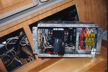
Fleetwood transfer switch
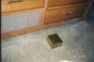
Inverter transfer switch from 1999 D
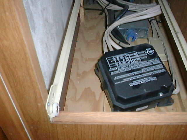
Here are some more pictures of transfer switches.
Transfer Switch - Interior
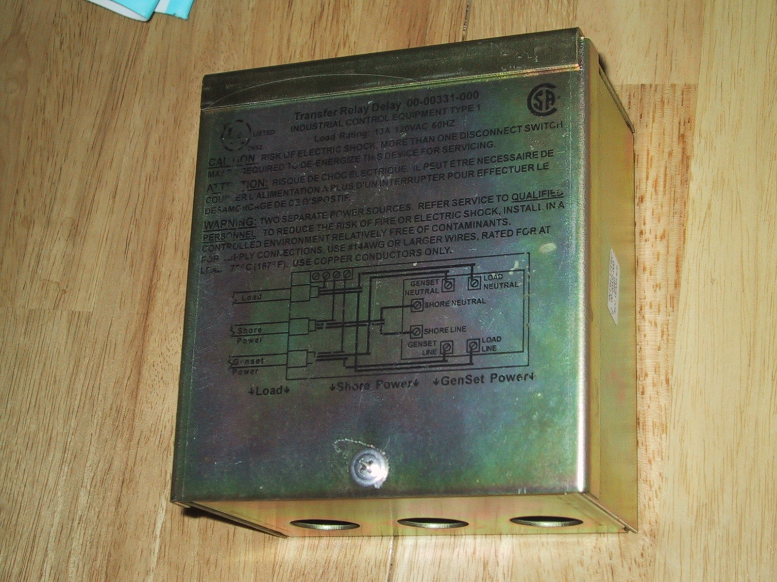
...and Exterior
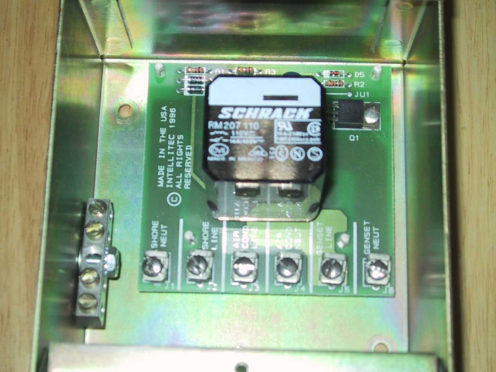
As a bonus, you now have a spare transfer switch, the same type as is used to switch between shore power and generator power.
After you have connected the three sets of wires together, the inverter output now goes to the junction of the three sets of wires that used to go to the transfer switch, and splits. Part of the power goes on into circuit #4 (PORTable APPLiances) to the front TV and the dinette outlet. Part of the power goes backwards through the "hot" line to the bottom of circuit breaker "port appl" (which we re-labeled "Inverter Output"), up through that 20 amp circuit breaker and out on the right hand bus bar. That power is now available for all the circuits on that right hand bus bar, that is all circuits except the air conditioners. The transfer switch within the inverter will sense incoming A/C power from shore or generator, turn off the inverter, pass the A/C power straight thru to the inverter A/C output, and power the right hand bus bar.
This modification do not exceed the seven branch circuit limit for the main electrical panel. The Heart Freedom 10 inverter output circuit does not need a separate circuit breaker if the total load does not exceed 20 amps (the size of the "TO INVERTER" input circuit breaker on the left bus bar).
Step 4. Make a neutral sub panel bus bar.
There is one additional modification, which must be made. As shown in the Heart installation guide, page 12, the neutral (white) wires of the left hand and right hand bus bars must not be connected together to prevent tripping the GFCI circuit breakers in many campgrounds. Look up into the bottom of the main panel, and trace the black and white wire pairs coming from the back and sides of the panel. All the black wires going to the right hand bus bar should have their corresponding white wires marked with a black mark. Then disconnect all four of the marked white wires of the right hand circuits from the "neutral" bar on the bottom right side of the main panel box. Get a small neutral bar connector strip from a builders supply store, or an electrical supply or a surplus house. Connect the four marked white wires to it, wrap the bar in electrical tape (two layers) and push into the bottom of the main panel box. Make sure it does not have an electrical contact with the metal box or the old neutral bus bar. Silicone it in place so that it wont rattle around and wear the tape away.
That's it. Put the cover back on the main electrical box, turn everything back on and enjoy.
MICROWAVE: In January at the Newport Rally, I met Dave Wickersham. He has been using a 1000-watt inverter to power his microwave for some time, and that is what prompted this project. The Freedom 10 inverter has a 12.5 amp "invert/charge" circuit breaker on the A/C output circuit. That means the inverter can put out 1500 watts without popping that circuit breaker. Dave said the Heart people told him (informally) that the 1000-watt unit could deliver 1500 watts for five minutes or so, but the microwave is marked to use 1600 watts, or 13.2 amp. So if you use the inverter to power the microwave, you will be overloading it. Be very careful. Use it only for those moments when you really don't want to use the generator. All of the other standard warnings about using the inverter still apply: Don't overload it by, for example, running the microwave and a hair dryer (1500 watts) at the same time. Don't leave the inverter on when you don't need it; it will suck your batteries down. Watch out for things like the refrigerator trying to automatically switch to A/C operation when the inverter is running (turn the AES switch to gas), remember that TVs and VCRs and the microwave and clocks use just a little bit of power all the time. If you have added an electric heating element in your water heater, make sure it is turned off as it will be better overall to heat your water with LP instead of using your batteries. Don't leave the 850 watt engine block heater on (switch light is out when heater is on) when the inverter is on. I've done all these things, and wondered why my batteries kept running down. But with a little learning, you can have convenient 110v electrical power all over your coach when you need it.
If you want to replace the 1000-watt inverter with a 2000-watt inverter, then you should make some additional changes to use the higher input and output power ratings of the unit. If you are interested in these, get in touch with me by e-mail at [email protected] and I'll discuss them with you. These involve using a thirty amp breaker on the main circuit panel for the input to the inverter (circuit #7), running a new #10 AWG wire from the main breaker panel circuit breaker #7 to the inverter instead of the #12 AWG wire currently there, and adding a 30 amp circuit breaker on the output of the inverter, using the space behind the blank panel on the main panel.
Submitted by Ed Kennedy #135, 98 34Q
The DISCOVERY OWNERS ASSOCIATION, INC, was formed to promote the sharing of information and the camaraderie of fellow Discovery motorhome owners. Membership in the club is limited to owners of Fleetwood Discovery motorhomes.