Copyright 2019 Discovery Owner's Association, Inc.

Diagnosis and Repair of Power Gear Leveling Control Module

Symptoms

A couple of months ago, while extending our Power Gear Leveling Jacks, the Jacks down light did not light, but the jacks went down OK. When we were ready to leave our location, and we raised the jacks, they only came up about 2/3 of the way. I ran them back down a bit, then raised them again and got them to come up all the way. We returned home without further incident.

Diagnosis

Determined to get to the bottom of this problem, I started the following procedure to find the problem.

  1. With the engine running, the park brake on, and the transmission in neutral, I turned on the jacks and extended them about 5 inches. No Jacks Down Light, No Alarm Bell
  2. With my foot on the brakes, I placed the transmission in Drive. No Jacks Down Light, No Alarm Bell.
  3. I placed the transmission in Neutral, and tried to raise the jacks. They came up about 3 inches. I dropped them a bit, then raised them again, and they fully retracted.

    NOTE: When I turned off the ignition I noticed the red jack down light flash which I interpreted as meaning the LED was good.

    Following the Power Gear Trouble Shooting guide (In Blue) I did the following:

  4. HARNESS WIRE FAULTY CHECK FOR +12 VDC AT FLUID SENSOR

    I removed the wire connector at the fluid sensor and tested for 12V when the Power Gear pad was turned on. 12V was present on the red wire.

  5. FLUID SENSOR MIS-ADJUSTED SEE TIP SHEET 30, 54 OR 81 FOR FLUID SENSOR ORIENTATION

    I inspected the sensor and it was properly aligned.

  6. FLUID SENSOR FAULTY CHECK FLUID SENSOR FOR CONTINUITY WITH JACKS EXTENDED, IF NO CONTINUITY, REPLACE SENSOR * CONTINUITY: PRE 2001 MODELS, RESISTANCE SHOULD BE NEAR ZERO. FOR 2001 AND NEWER UNITS, RESISTANCE SHOULD BE NEAR 1000 OHMS

    I ran the jacks down until they touched the ground, then measured the continuity of the sensor. It was correct.

  7. OPEN ON THE BROWN WIRE CHECK FOR CONTINUITY BETWEEN BROWN WIRE AT FLOAT SENSOR and the BROWN WIRE AT CONTROL.MODULE * IF NONE REPLACE WIRE.

    To test this I ran a wire from the Brown wire at the fluid sensor to the dash area, removed the front cover under the dash, then using a digital multimeter checked for continuity on the Brown wire at the control. Module. I found the wire to be OK. I turned on the Power Gear Jacks and the Jack Down light lit for a few seconds then went out.

Solution

With this information, I removed the control module, removed its cover, and then the circuit board. One corner of the circuit board where the hydraulic control wire connector connects was badly corroded, and the brown wire circuit and post were corroded away. After tracing the circuitry on the board I found a location where I could solder a jumper wire to replace the corroded post. Once repaired all systems worked as they are supposed to work. This also means the alarm circuit is only activated when the Jacks Down (Brown) wire is energized by lowering the Jacks.

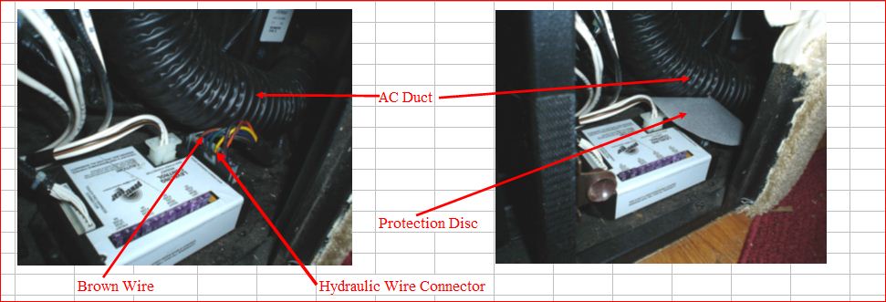
Now to find the reason for the corrosion. It turns out the AC duct work passes right over the leveling control module. When using the Dash Air, condensation from the AC duct dripped down onto the hydraulic connector wires eventually causing the failure. The solution was to fabricate a protection disc to slide over the wires and cause any condensation to fall harmlessly onto the floor where it evaporates without causing further damage. The following PICs illustrate the location of the control module with and without the protection disc.

Submitted by Jim Fox

WHO WE ARE

The DISCOVERY OWNERS ASSOCIATION, INC, was formed to promote the sharing of information and the camaraderie of fellow Discovery motorhome owners. Membership in the club is limited to owners of Fleetwood Discovery motorhomes.

GET IN TOUCH

Website Questions
Email Webmaster
Membership Questions
Email Membership Coordinator

SEARCH THIS SITE