

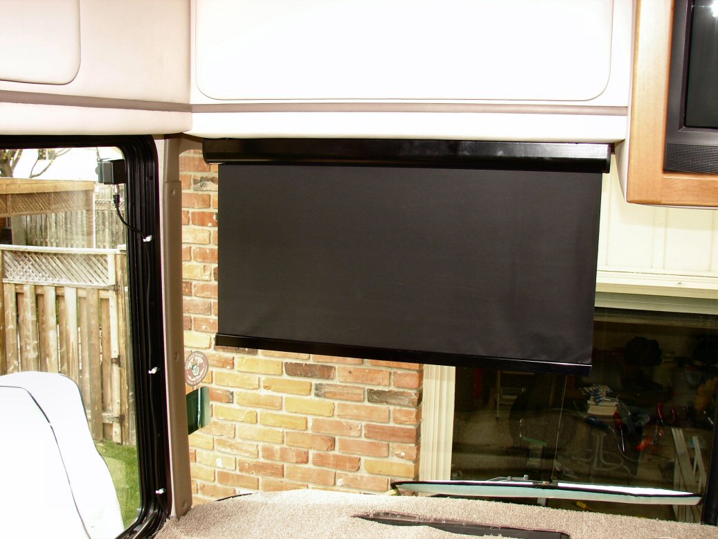
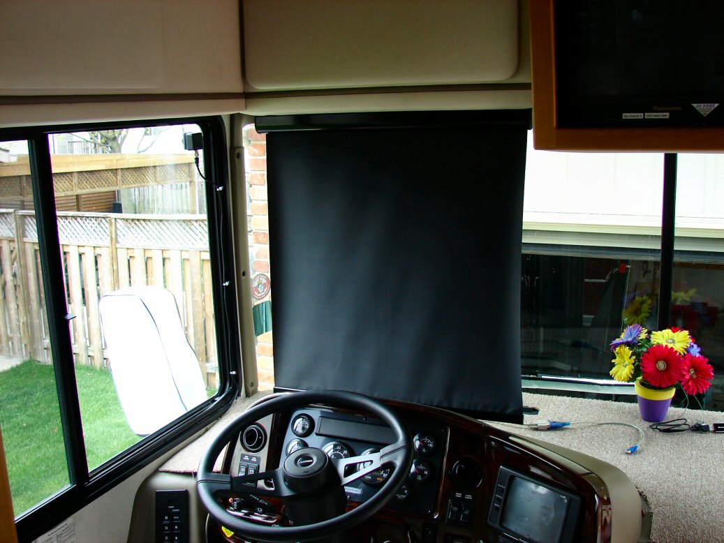
This is the installation on my 1999 D. I bought a power smart visor from Carefree. It is the 30" left hand motor and it comes with all the wiring, switch and instructions. I also bought a small fuse holder and some 5 amp fuses, 10' of 1/4" black flexible corrugated split tubing to put over the power feed up to the visor and some 6" and 4" cable ties.
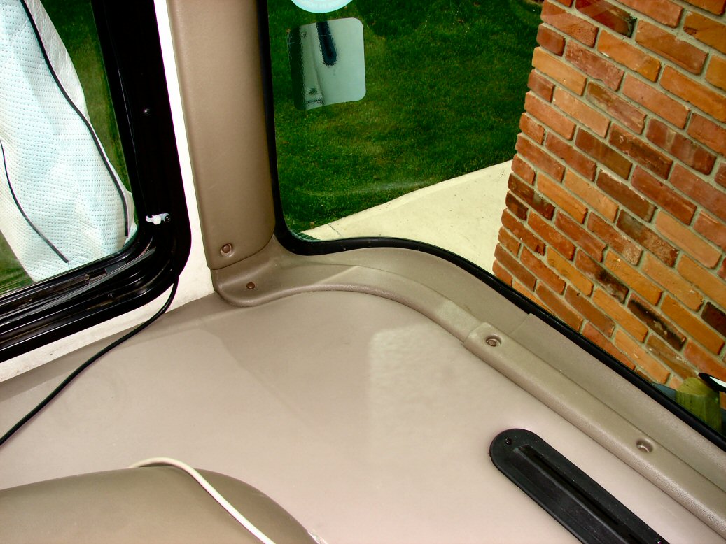
I removed the original sun visor took off the black mounting plates and mounted the mounting plates back on to cover the marks in the padded material. Then I popped off the screw caps and removed the screws holding the long plastic cover on the road side of the windshield, the lower corner plastic molding and 4 screws holding the front curtain track in that area for more clearance so I could get the top corner plastic molding off. There are a few wires running in this area already but there is lots of room to run the 1/4" split tubing with the new wire inside. I would like to remove more of the trim under the curtain track so I could hide the wires from the visor but was not sure how to.
I then took the 1/8" plywood cover off the bottom of the driver side arm console to select a place to mount the switch and noting where the other wires ran . I used a 1" round hole saw and carefully drilled out a hole in the plastic and fed the wires to the visor and power with the switch attached through and out the front end of the consol. The switch has a sticky material covered with clear plastic but don't glue it down yet as you don't know which way the switch makes the visor move.
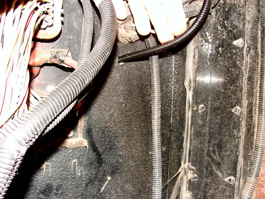
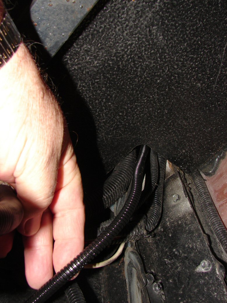
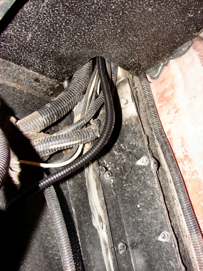
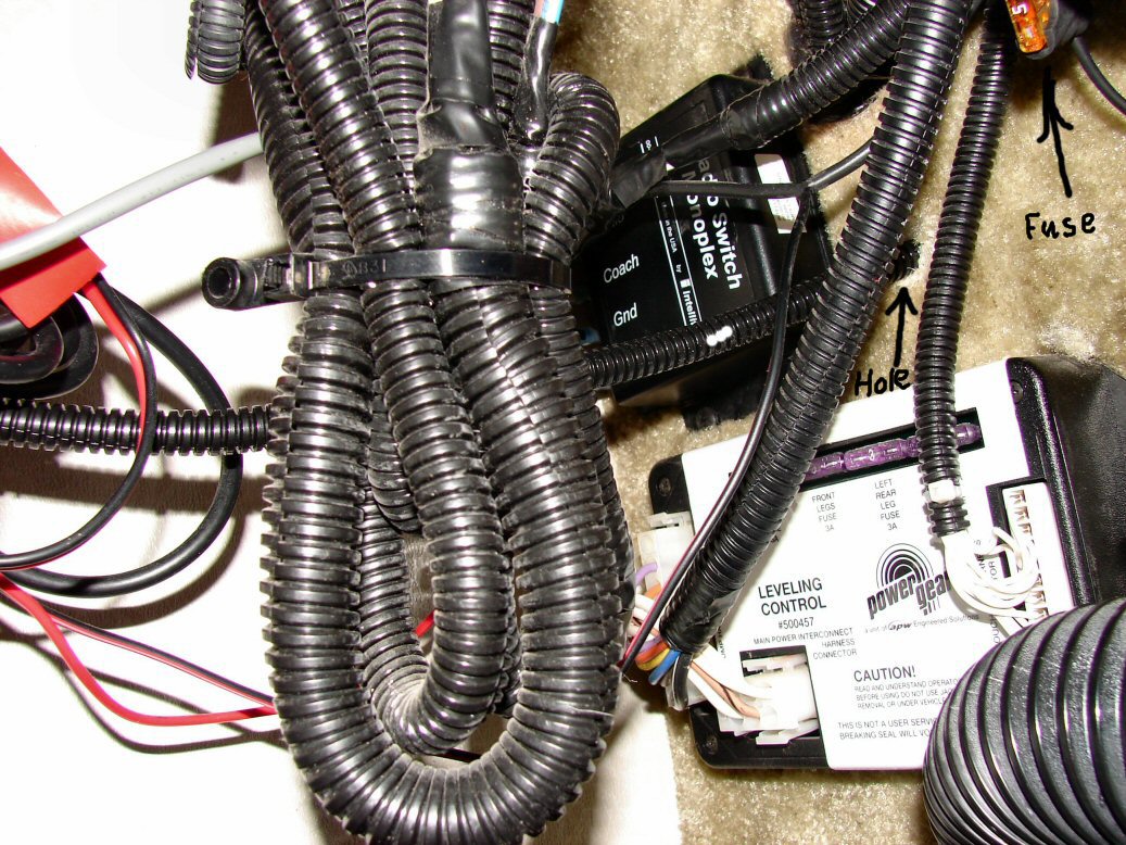
You will have to drill a hole through the front plywood bulkhead with about a 3/8" twist drill. I drilled mine in line with were the wires left the arm console but MAKE SURE there are no cable harnesses near where you are drilling on both sides. I then pulled the gray wire going to the visor through all the way.
At this point I slid on the 1/4" black flexible corrugated split tubing and found it did not slide too far so I tied the wire end to something solid and I was able to slide the 1/4" split tubing the right through the bulkhead hole all the way to the switch. I now fed the wire and split tubing up through the top hole into the dash area. Inside I strung the wire/tubing up to the top and cable tied them all in place. There is about 8 feet of wire left over which you will have to cut off and you can use some of it to run to power and ground as the wires off the switch are short.
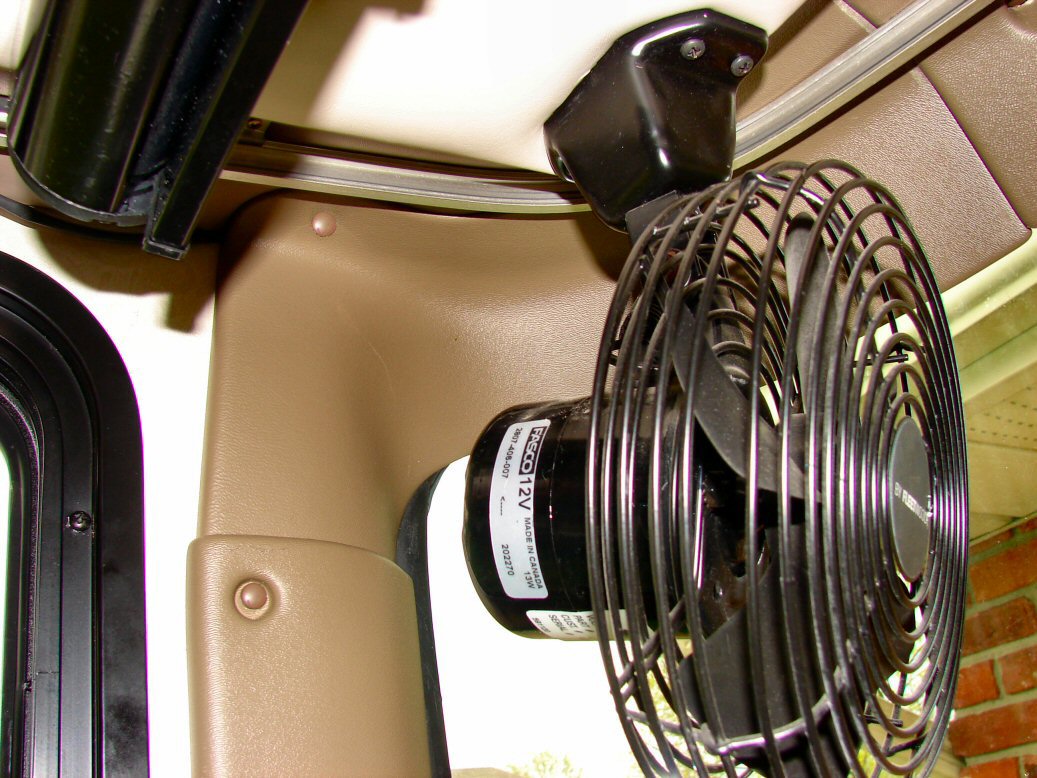
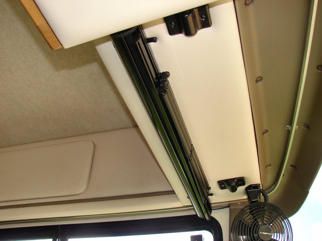
Toughest job is to mount the visor as only one person can fit in there. The 30" visor covers the full length of were the old visor sat. I rotated the fan in that corner so at its widest point of the wire fan shield would not touch the visor as it traveled up and down. Also tried to get it straight and marked one screw hole with a pen then with a power drill screwed that corner of the visor mount in but not tight and gently released the visor to get another screw and reposition myself. I straightened the visor as best I could and screwed in the opposite corner.
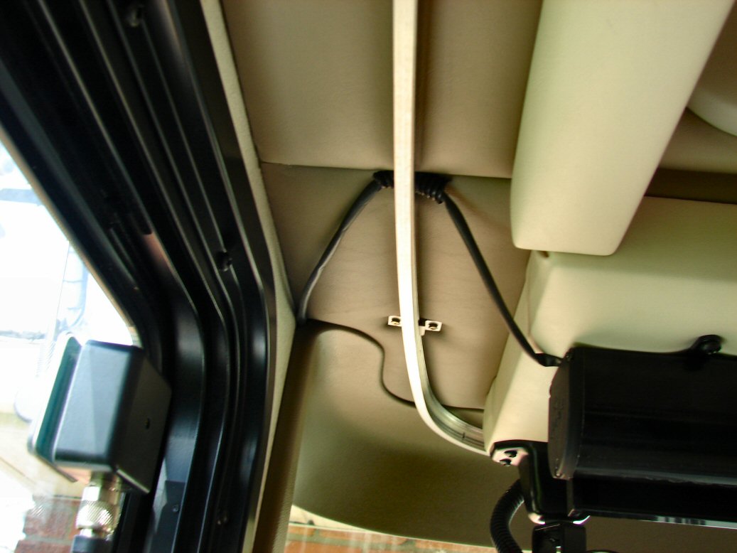
I pulled the wires from the visor under the curtain rail and added a trimmed bit of 1/4" split tubing were the wires went under the metal rail to protect if from chafing. Now butt crimp (red) the matching colored wires together and cut a little bit of the corner out of the top plastic molding where the wire passes through and replace all the covers.
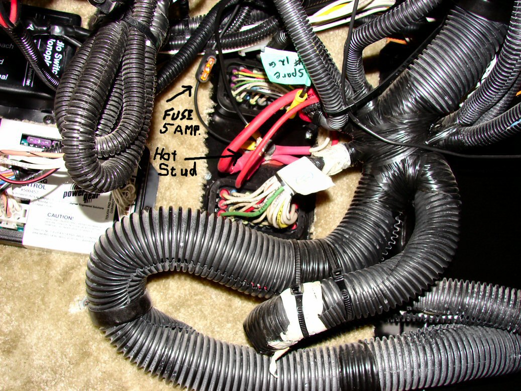
For power I decided to tie into the OEM positive power stud (9/16" nut) on the front bulkhead. MAKE SURE to turn off both disconnects and shore power now disconnect the negative wires on the chassis batteries as this stud is fed directly from the battery through a 135 amp circuit breaker. I crimped on the fuse holder then used a yellow ring crimp connector that would fit over the stud (Blue would be better but I didn't have one) and then crimped on the wire to the switch on the butt connector on the fuse holder and added an extra connector and short piece of wire ending in a butt connector for future power use. I then removed the nut, slid the two ring connectors over the stud replaced the nut then connected the black negative wire from the visor switch using a blue ring butt connector to a screw attached to the metal around the bottom of the steering wheel mount. Now I turned on shore power and disconnects and inverter.
I tested the visor up and down and decided how I wanted the switch to sit then removed the thin plastic shield over the sticky base of the switch and stuck it down. I also put some black automotive silicone around were the 1/4" split tubing passed through the bulkhead.
I took a few pictures though a little late, to help visualize what I did. Hope this helps.
Submitted by - Al Macklin

The DISCOVERY OWNERS ASSOCIATION, INC, was formed to promote the sharing of information and the camaraderie of fellow Discovery motorhome owners. Membership in the club is limited to owners of Fleetwood Discovery motorhomes.